Tutorial: tolerance allocation in PTC Creo
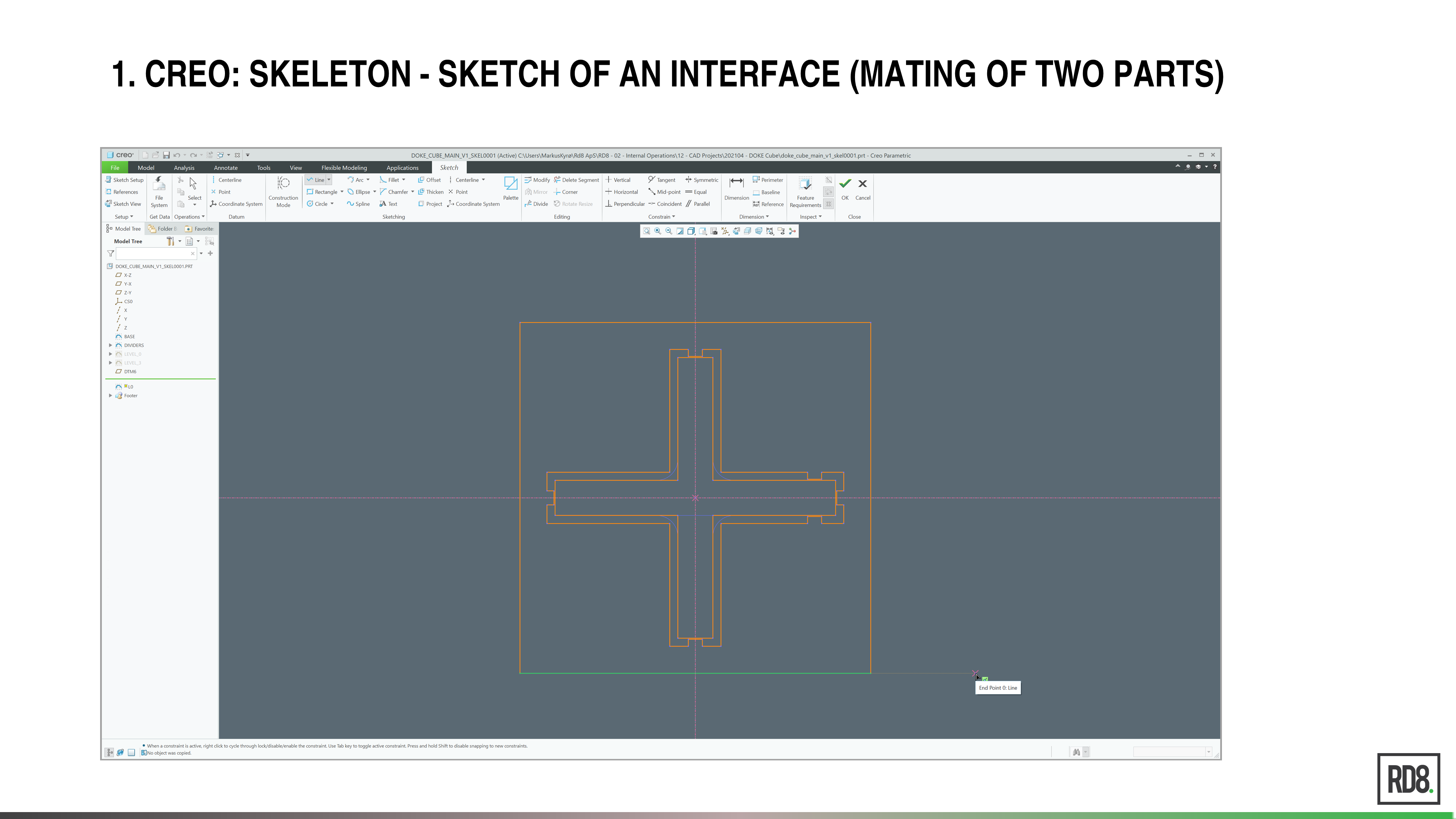
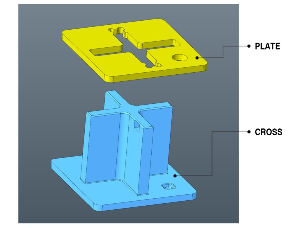
This tutorial will show how to do tolerancing in CAD software. An example of an interface sketch (in a PTC Creo skeleton model) between two mechanical components – a “CROSS” and a “PLATE” will be used.
Step-by-step guide – tolerance allocation in PTC CREO 6.0 (CAD software)
Tutorial for tolerance setting by an example in PTC Creo.
- IN CREO –> OPEN A SKETCH CONTAINING THE INTERFACE BETWEEN TWO PARTS
- In this example, the sketch is a part of a skeleton model in Creo 6.0 and represents the mating between two parts – a “CROSS” and a “PLATE”
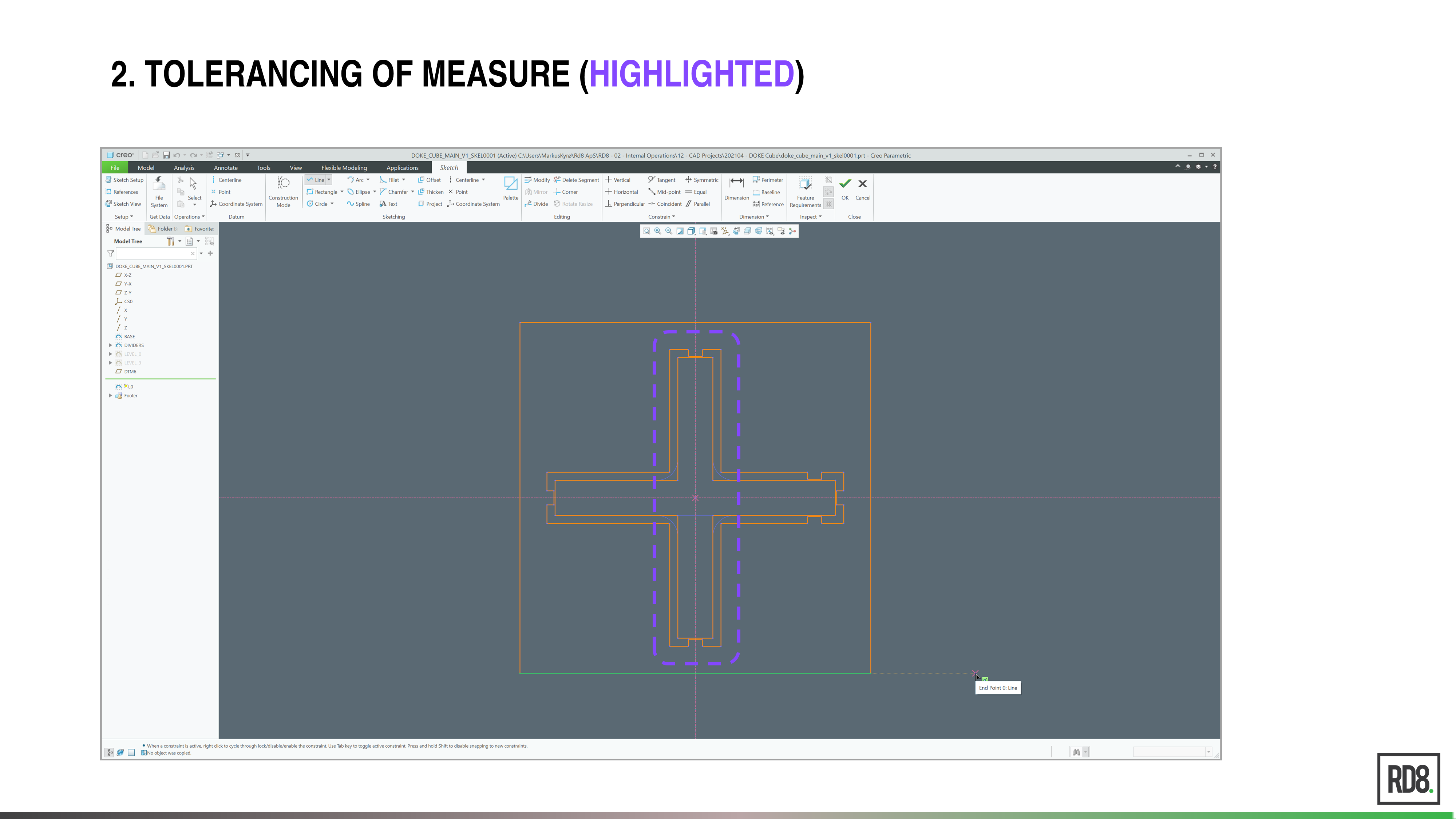
- IDENTIFY THE FIT THAT SHOULD BE TOLERANCED
- In this case, it is intended to make as close a fit as possible without overlap of the parts
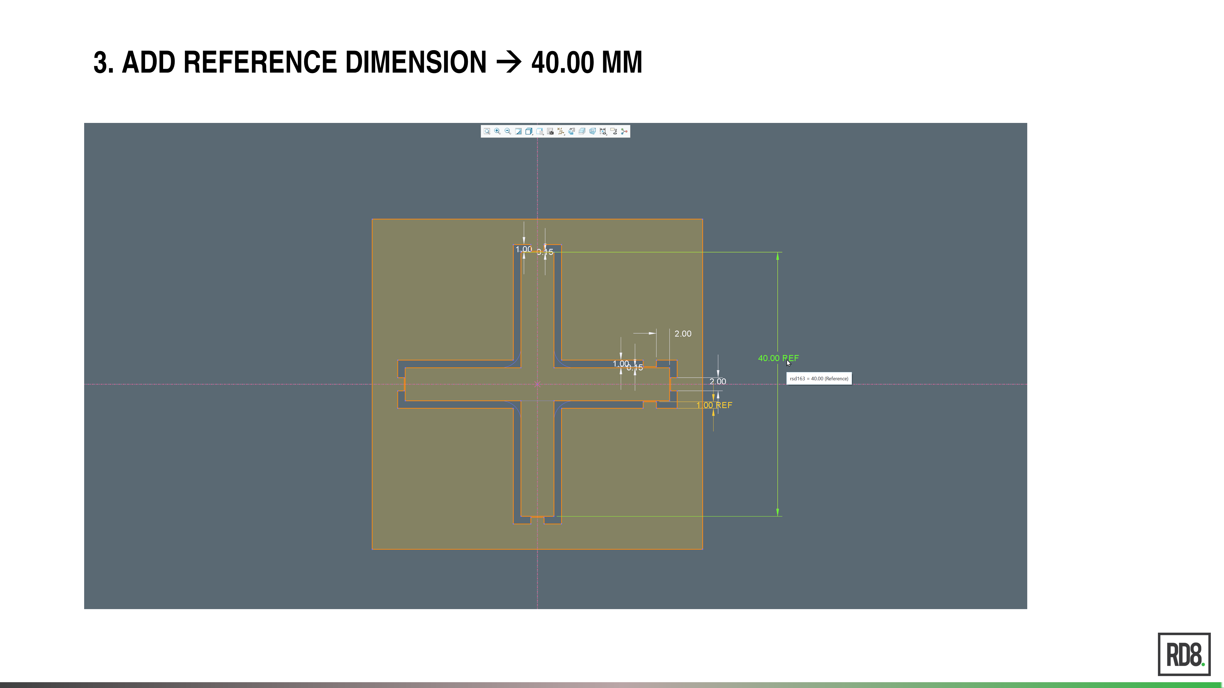
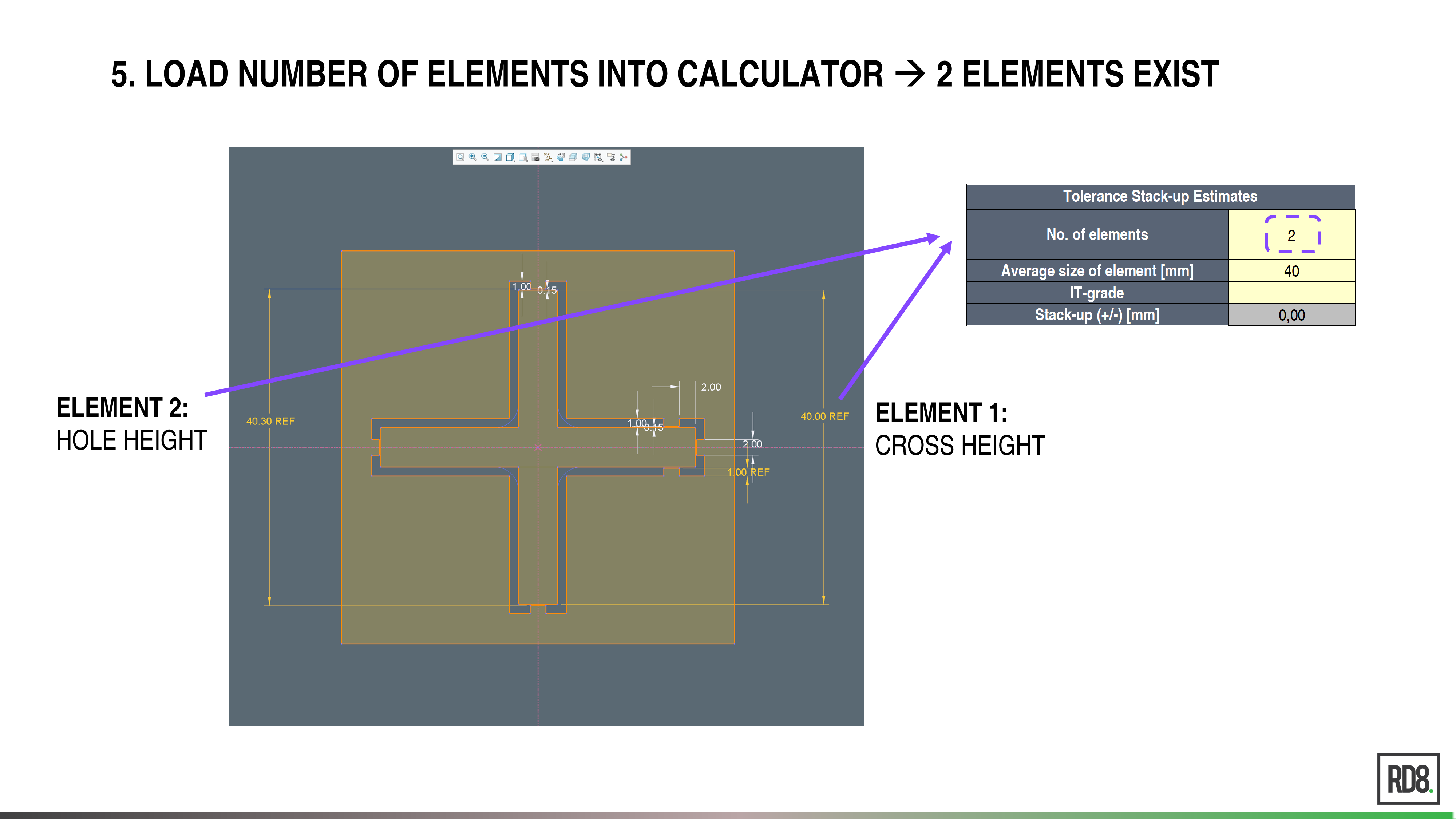
- ADD A REFERENCE DIMENSION TO THE SKETCH
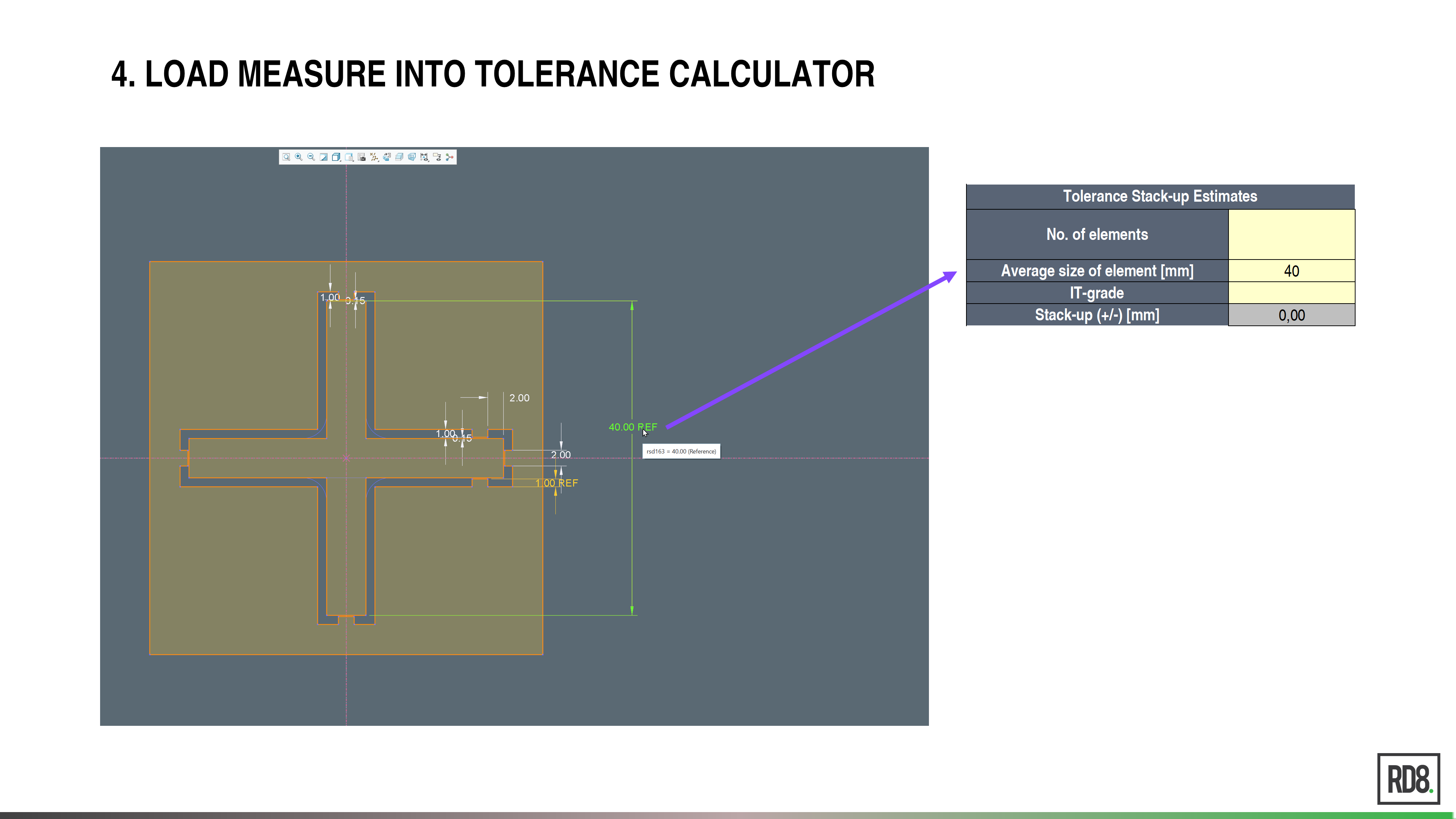
- READ THE GIVEN DIMENSION AND LOAD THE MEASURE INTO THE RD8 TOLERANCE STACK-UP CALCULATOR
- In this case, 40 mm
- The RD8 Tolerance Stack-up calculator can be found here
- INSERT THE NUMBER OF ELEMENTS INTO THE CALCULATOR
- In this case, there are two elements – the height of the CROSS and the height of the hole in the PLATE part.
- ENTER THE IT-GRADE OF THE GIVEN PRODUCTION PROCESS
- In this case – IT11 for laser cutting
- See RD8 documentation for IT-Grades and recommended IT-bands
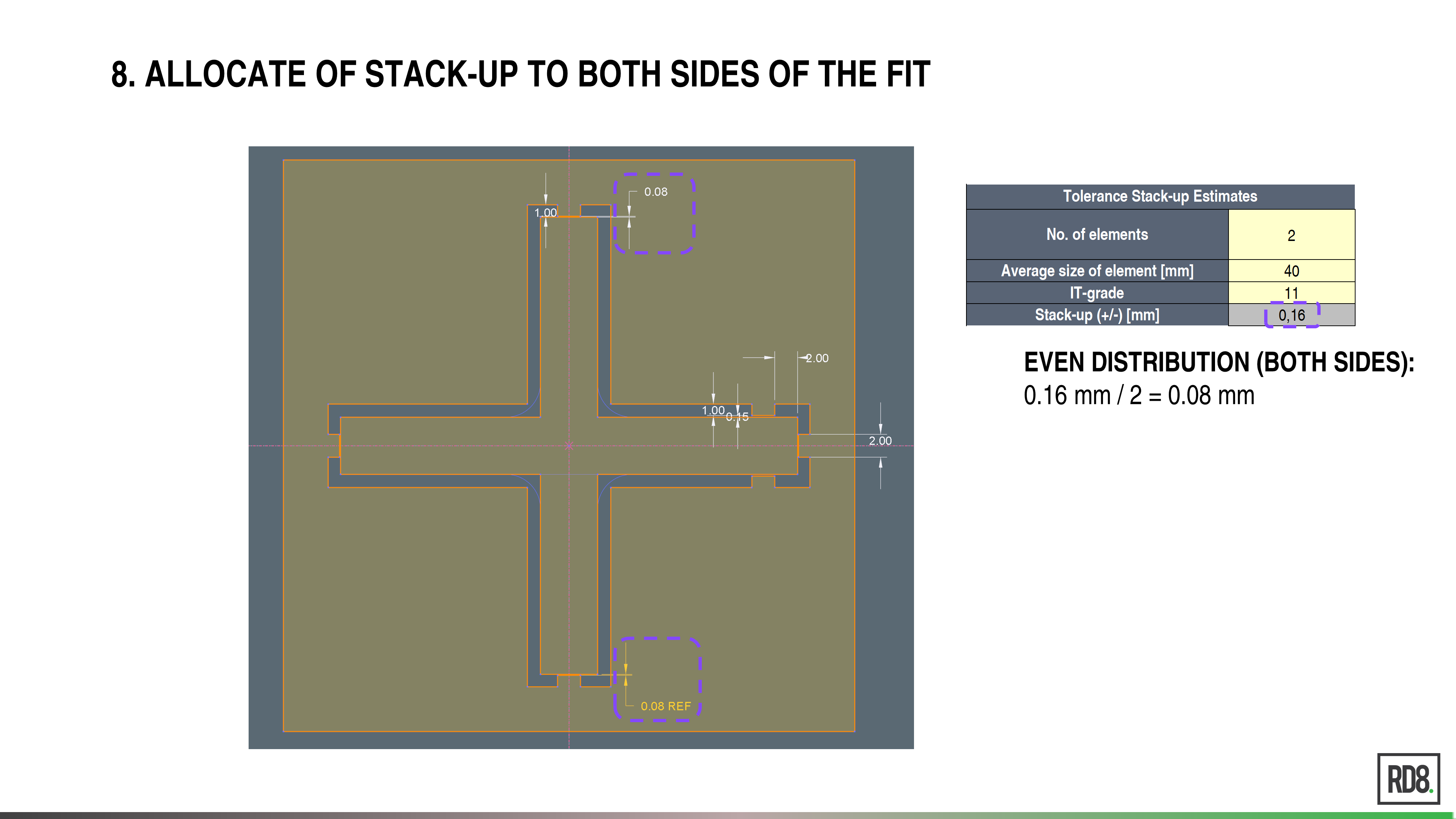
- READ THE OUTPUT OF THE CALCULATOR
- In this case: +/- 0.16 mm
- ALLOCATE THE TOLERANCE TO THE FIT
- In this case, tolerance is added to the top and bottom of the sketch. The 0.16mm could also be allocated to one side only.
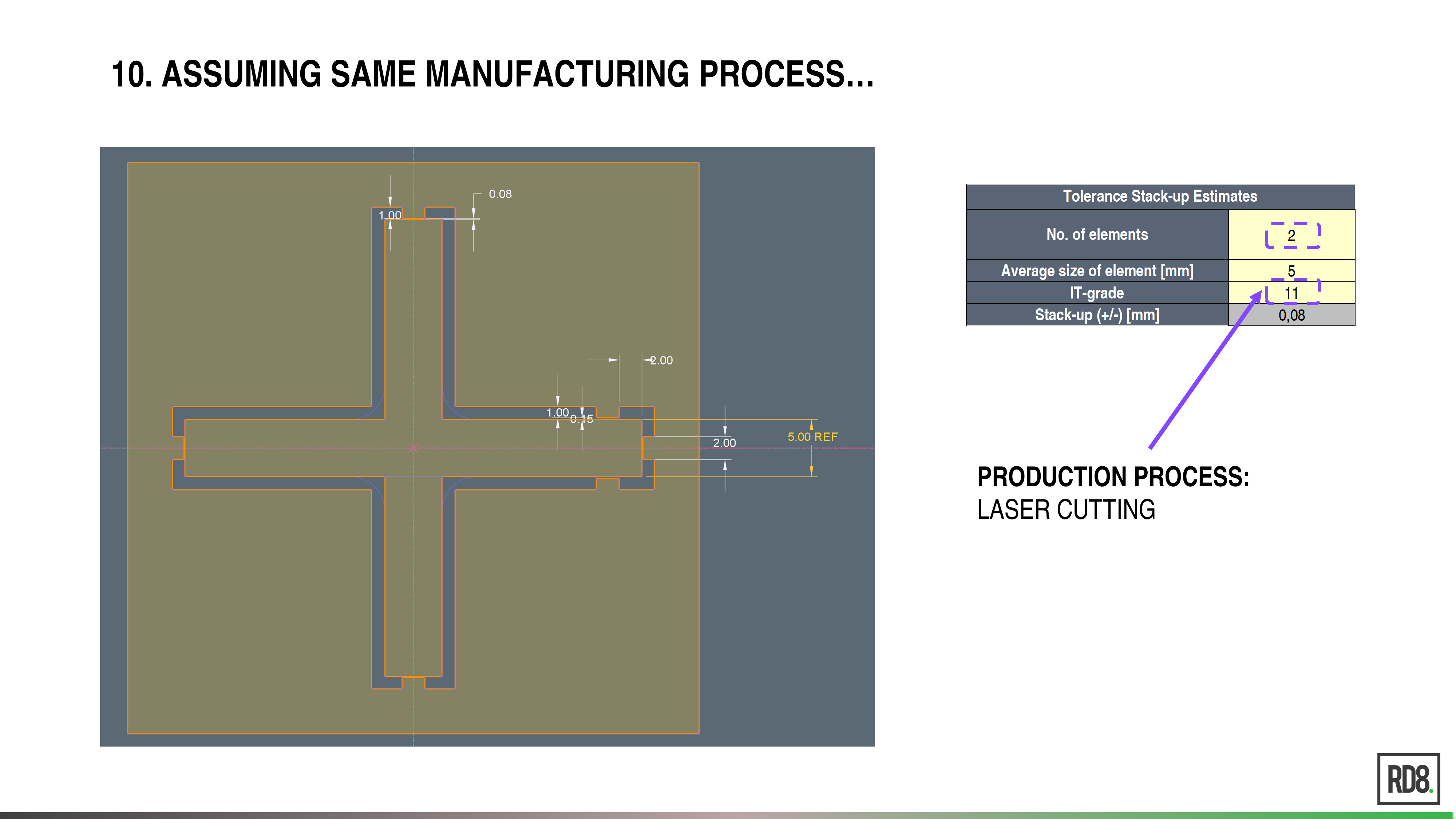
- EXAMPLE OF A FIT ON A SMALLER MEASURE (OF 5 MM)
- ASSUMING THE SAME MANUFACTURING PROCESS
- Still assuming that the parts are made by laser cutting processes (IT-Grade = IT11)
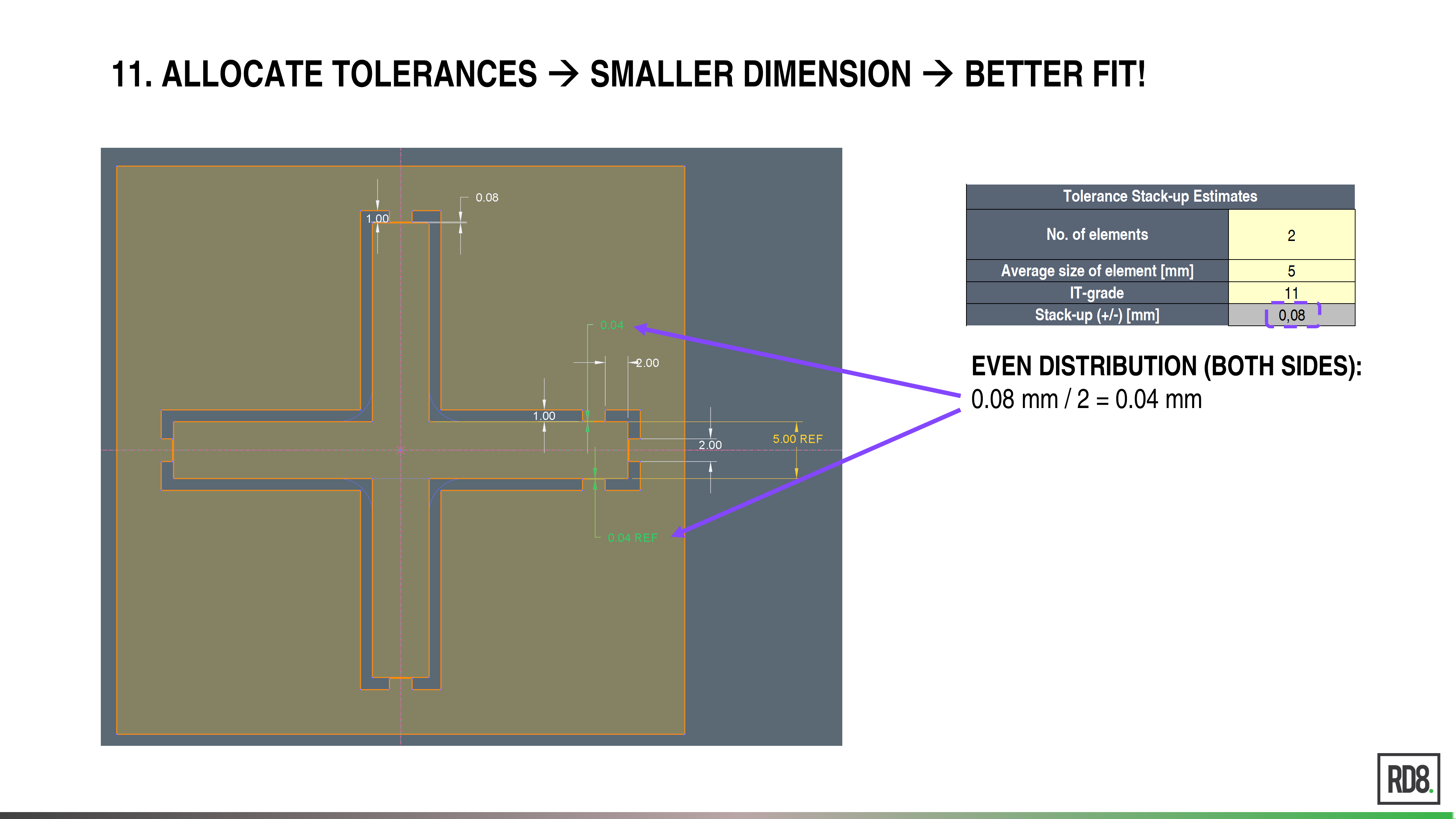
- READ OUTPUT AND ALLOCATE TOLERANCES TO FIT!
- It is seen that the tolerance stack-up is smaller for smaller dimensions
- This reduces the variation of fits
TAKEAWAY
If a minimum variation is intended (a Robust Design), then the important fits should be placed on small dimensions!- IN CREO –> OPEN A SKETCH CONTAINING THE INTERFACE BETWEEN TWO PARTS

